Motorized Dalek Head:

Description and Purpose of this page.

The Doctor Who pinball machine has a Dalek head on top of the backbox, in under 100 prototypes, this head contains a motor to allow for the head to swivel from left to right in coordination with the speech.

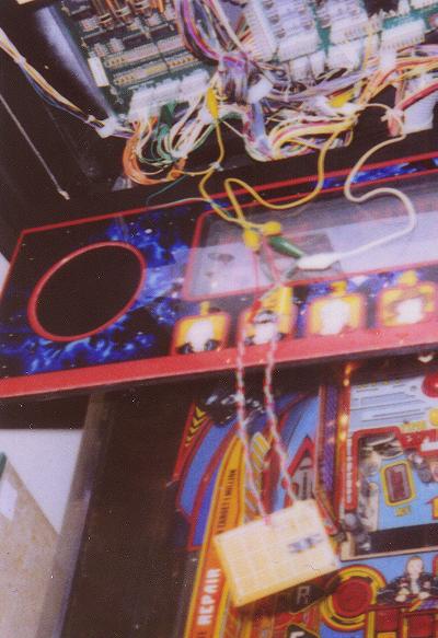
All Doctor Who pinball machines have the software necessary to control the Dalek head. Unfortunately, apparently due to cost overruns, the motor and all associated wiring was left out in all but these few prototypes. In all non-prototype machines, the top of the head is simply glued to the bottom and a flasher is the only thing mounted inside the head.

This page contains the info that I collected, and my method of creating and installing a motorized Dalek head and all associated additional circuitry in my Doctor Who Pinball machine. Several of the smaller pictures have links to larger pictures which will open in their own window with some pointers to parts.

Under most circumstances, I tried to do as professional a job as I could do. I hope this is reflected in the pictures on this site as well as the descriptions.

Order in which I created the Dalek head.

  1. Building the Opto switch. (Under Construction)
  2. Building the Voltage regulator (Under Construction)
  3. Creating all the connections for the Motor and Switch.
  4. Creating all the connections at the plug and harness.
  5. Building the mount for the Motor, Switch and Flasher.
  6. Getting a motor for the mechanism.
  7. First placement of items on mount.
  8. Building the Opto Separator
  9. Final mounting of motor, switch and flasher on pin.
  10. Final testing and adjustments
  11. A finished motorized Dalek head!
  12. A partial listing of the components I used
Note: Where not otherwise noted, part numbers in parenthesis are Radio Shack part numbers.

Pfutz also has a page on info about the motorized Dalek head, with a detailed pictorial disassembly of an original prototype mechanism and MPEG's of operational heads. You can get to that page, here.

1: Building the Opto switch.


Front of Board

Back of Board

Schematic Diagram
Parts Used:
  • Opto Pair (276-0142)
  • 470 Ohm Resistor (271-1115)
  • Circuit Board (276-0149)
  • 4 Pin Male Plug (274-0224)

Opto switch connections.


   Opto Board Plug (4 Pin Male - 274-0224)
      
      Pin:    Connection:
      ----    ------------------------------ 
       1      IR Rcvr - Opto Row
       2      IR Rcvr - Opto Column
       3      IR Xmtr - Ground
       4      IR Xmtr - +12 VDC

First testing of Opto switch.


  • During first testing, I hadn't yet connected all the wiring as detailed below, so the Opto switch was connected with jumper wires.
  • Be very careful not to get the wires backwards...
    • +12 VDC applied directly to the IR Receiver will destroy it pretty quickly.
    • This was from experience as I had to replace it once.

2: Building the Voltage regulator.


Front of Board

Back of Board

Schematic Diagram
Parts Used:
  • Adj Voltage Regulator - LM317T (276-1778)
  • 4.7 KOhm Micro Potentiometer (271-0281)
  • 0.1 MicroFarad Capacitor (272-0135)
  • 220 Ohm Resistor (271-1111)
  • Circuit Board (276-0148)
  • 4 Pin Female Plug (274-0234)
  • 2 Pin Male Plug (274-0222)
  • Voltage regulator is used to lower the 20 VDC Solenoid voltage to a 12 VDC Source (Measured as +12.01 VDC by my voltmeter from Output to Ground on my system) that runs the motor at approximately the correct speed (~20 RPM)

Voltage regulator connections.


   Voltage Regulator Plug (4 Pin Female - 274-0234)
   
      Pin:    Connection:
      ----    ------------------------------
       2      +20 VDC (Power 1)
       3      Ground
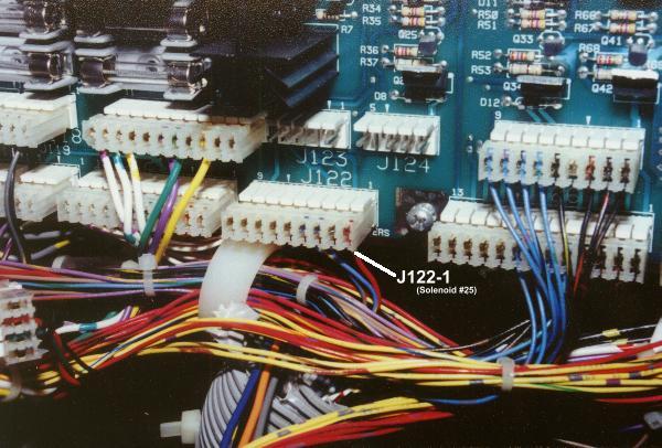
       4      Motor Control (Solenoid #25)

   Motor Power Plug (2 Pin Male - 274-0222)
   
      Pin:    Connection:
      ----    ------------------------------
       1      Positive Variable Voltage
       2      Motor Control (Solenoid #25)


3: Creating all the connections for the Motor and Switch.


  • Opto switch's Row/Column and the Solenoid Power must be spliced from J208-1, J206-9, J107-5 and J107-6.
  • +12 VDC power and ground for the Opto Switch must be added from J118-2 and J118-3.
  • Wiring for the Motor control must be added from J122-1.

Splicing the Opto's Row/Column and Solenoid Power.


Parts Used:
  • 2 Telephone Splice Connectors (64-3080), one for each of the two wires for the opto switch.
    • Row: J208-1
    • Column: J206-9
  • 2 Tap-In Squeeze Connectors (64-3053), one for each of the two +20 VDC wires for the Motor power.
    • Power 1: J107-5
    • Power 2: J107-6
  • For splicing of Row/Column, I went just a little downstream of where the board connections were and made the splice.
  • For splicing of Solenoid/Motor Power, I followed the wires down to just before they go into the lower area which is a better area in my opinion for splicing them.
  • For the wiring, I used individual telephone line wire for the Row/Switch and some larger gauge wire for the motor voltage wire, all of which I ran alongside the preexisting wire to a plug at the top of the backbox.

Adding wiring for power and ground for the Opto Switch.


Parts Used:
  • Prexisting Connector Plug for +12VDC Power from the correct pins which originally run power to the lights in front of the Dalek Head.
    • +12 VDC: J118-2
    • Ground: J118-3
I simply pressed the two new wires into the plug connector alongside the preexisting wires.
  • For the wiring, I used 2 pieces of normal gauge hookup wiring which I ran alongside the preexisting wiring to a plug at the top of the backbox.

Adding the wiring for the Motor control wire.


Parts Used:
  • Original plug connector at the board for the Motor control(Solenoid #25) - an empty connector location on the plug.
    • Control Wire: J122-1
I simply pressed the new wire into the plug connector at the correct location.
  • For the wiring, I used a piece of normal gauge hookup wiring which I ran alongside the preexisting wiring to a plug at the top of the backbox.

4: Creating all the connections at the plug and harness.


Wiring Diagram
  • All wires spliced/added from the board connections previously made and routed to the top of the backbox must now be connected to the 9-Pin Plug (Male)
  • After the 9-Pin Plug is created, a 9-Pin (Female) Socket must be used with a 4-Pin socket (Female) and a 4-Pin Plug (Male) to make a harness that will go between the Main plug, the Opto Switch and the Voltage Regulator.
  • Recommendation: Wire tie the wires of the two 4 Pin Plug/Socket such that they can't possibly be plugged into each other (Would kill something, I'm sure)

Connections for the Main Plug and Harness


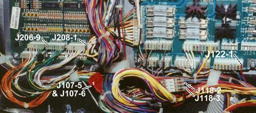
   Main Plug Connections (9-Pin Male - 274-0229)

      Pin:    Connection:                     From:
      ----    ------------------------------  ------
       1      Opto Switch #81 - Row           J208-1
       2      Opto Switch #81 - Column        J206-9
       5      Ground                          J118-3
       6      +12 VDC                         J118-2
       7      +20 VDC (Power 2)               J107-6
       8      +20 VDC (Power 1)               J107-5
       9      Solenoid #25 Control            J122-1

   Harness Plug Connections (9-Pin Female - 274-0239)
   
      Pin:    Connection:                     
      ----    ------------------------------
       1      Opto Board Plug  - No. 1
       2      Opto Board Plug  - No. 2
       5      Opto Board Plug  - No. 3
              Voltage Reg Plug - No. 3
       6      Opto Board Plug  - No. 4
       7      Voltage Reg Plug - No. 1
       8      Voltage Reg Plug - No. 2
       9      Voltage Reg Plug - No. 4
      
   Harness Opto Board Plug (4 Pin Female - 274-0234)
      
      Pin:    Connection:
      ----    ------------------------------ 
       1      Harness 9-Pin Plug - No. 1
       2      Harness 9-Pin Plug - No. 2
       3      Harness 9-Pin Plug - No. 5
       4      Harness 9-Pin Plug - No. 6
       
   Voltage Regulator Plug (4 Pin Male - 274-0224)
   
      Pin:    Connection:
      ----    ------------------------------
       1      Harness 9-Pin Plug - No. 7
       2      Harness 9-Pin Plug - No. 8
       3      Harness 9-Pin Plug - No. 5
       4      Harness 9-Pin Plug - No. 9


5: Building the mount for the Motor, Switch and Flasher.

Creating the mounting plate and mount mechanism.


Mount from Front

Mount from Back

Mount from Bottom
Parts Used:
  • Mostly just sheet metal bent to the correct shape.
  • Several screws.
  • Several Nuts and Washers.
  • As well as a few wingnuts.

6: Getting a motor for the mechanism.

Main motor connections.


   Motor Power Plug (2 Pin Female - 274-0222)
   
      Pin:    Connection:
      ----    ------------------------------
       1      Motor Connection 1
       2      Motor Connection 2


7: First placement of items on mount.


Front View
Back View
Top View
Parts Used:
  • Screws
  • Washers
  • Nuts

8: Building the Opto Separator.


Parts Used:
  • Sheet Metal bent for the separator
  • 2 Steel spacers
  • 1 8/32 Screw
  • 8/32 Tap for threading the hole in the spacers

9: Final mounting of motor, switch and flasher on pin.


10: Final testing and adjustments.


11: A finished motorized Dalek head!

Various images of the Dalek head, just after final construction and in motion.

12: A partial listing of the components I used


   - Motor and Mount
     - Motor                             Williams PN:  14-7976
     - Mounting System (Mostly bent, doubled over Sheet Metal)
   - Opto Switch
     - Opto Pair                                    - 276-0142
     - 470 Ohm Resistor (Pack of 5)                 - 271-1115
     - Circuit Board                                - 276-0149
   - Voltage Regulator
     - Adj Voltage Regulator (LM317T)               - 276-1778
     - Micro Potentiometer (4.7 KOhm)               - 271-0281
     - 0.1 MicroFarad Capacitor (Pack of 2)         - 272-0135
     - 220 Ohm Resistor (Pack of 5)                 - 271-1111
     - Circuit Board                                - 276-0148
   - Tapping of Solenoid Voltage
     - Tap-In Squeeze Connectors (Pack of 7)        -  64-3053
   - Tapping of Switch Row/Column
     - Telephone Wire Splice Connectors (Pack of 4) -  64-3080
   - Assorted Connectors
     - 9 Conductor Male   - Molded Nylon Connector  - 274-0229
     - 9 Conductor Female - Molded Nylon Connector  - 274-0239
     - 4 Conductor Male   - Molded Nylon Connector  - 274-0224 (x2)
     - 4 Conductor Female - Molded Nylon Connector  - 274-0234 (x2)
     - 2 Conductor Pair   - Molded Nylon Connectors - 274-0222
   - Useful, But Not Required
     - Pin Extractor For Connectors                 - 274-0223
   - Assorted Wires, Soldering Iron, Solder, Screws, Nuts, Etc...


Main * Game Story * Background * Terminology
Game Rules * Locations * Promotional Stuff * Dalek Head

Last Updated: 14 Apr 00